Diesel Fuel System Diagram
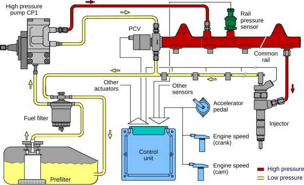
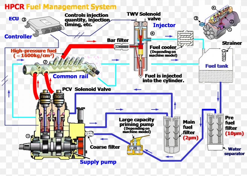
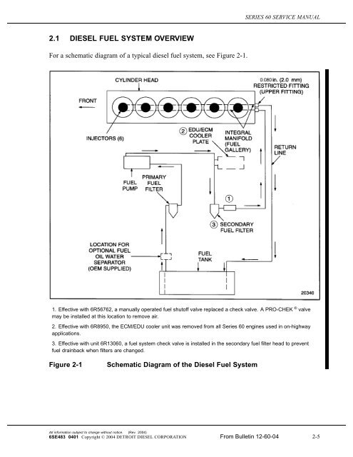
Diesel fuel system diagram. Less for rotary fuel injection pumps or 20 cSt viscosity or less for other fuel injection pumps. From the fuel filter fuel flows through the MCM cooler to the fuel pump. High Pressure Fuel Injector Lines 11.
Look in your service manual for the wiring diagramMar 31 This is my way of removing air from fuel system of dodge cumminsFeb 03 Heres a redneck diagram of the fuel system on a CUmmins ISLISC engine. 5 9 Cummins Engine Fuel System Diagram - Welcome to our website we try to bring you relevant images to what you are looking for about 6 5 Diesel Fuel System Diagram 14 PicsTherefore we present the picture. A fuel injection system consists of.
Cummins B Series engine - Wikipedia. After that it goes to the mixing column through a filter and flow meter. 3 Via Standards tables the equivalent specific gravity using the ASTM D287 test method temperature of.
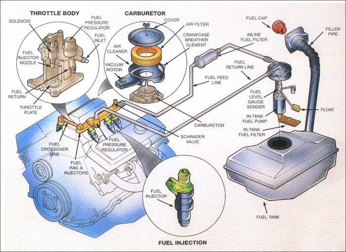
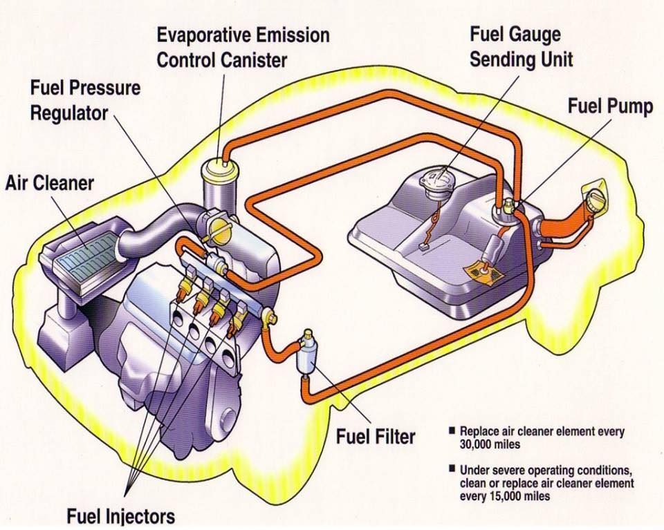
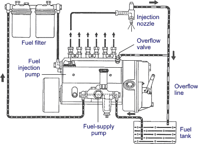
Fuel injection system construction. 7 3 diesel fuel line diagram wordpress new 7 3 ford powerstroke sel fuel pump kit 94 597 features fuel pump included new carter fuel pump 1 ford 7 3 diesel fuel system diagram read more. Needle Return Pressure Control Valve 14.
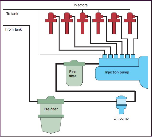
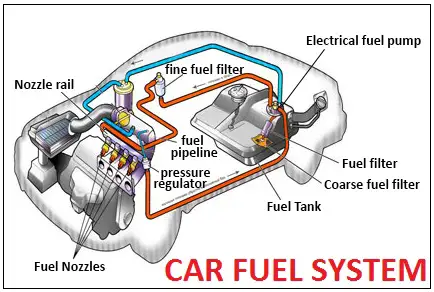
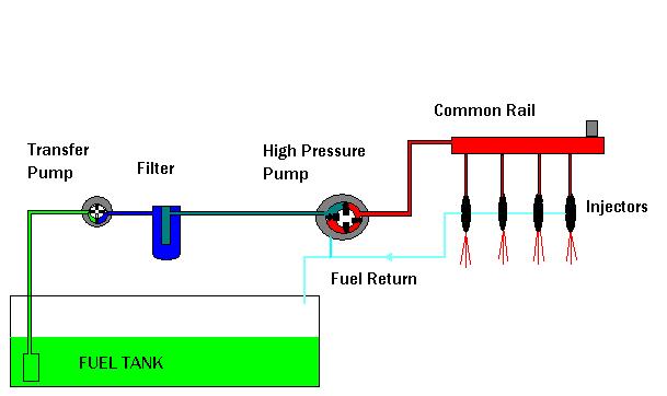
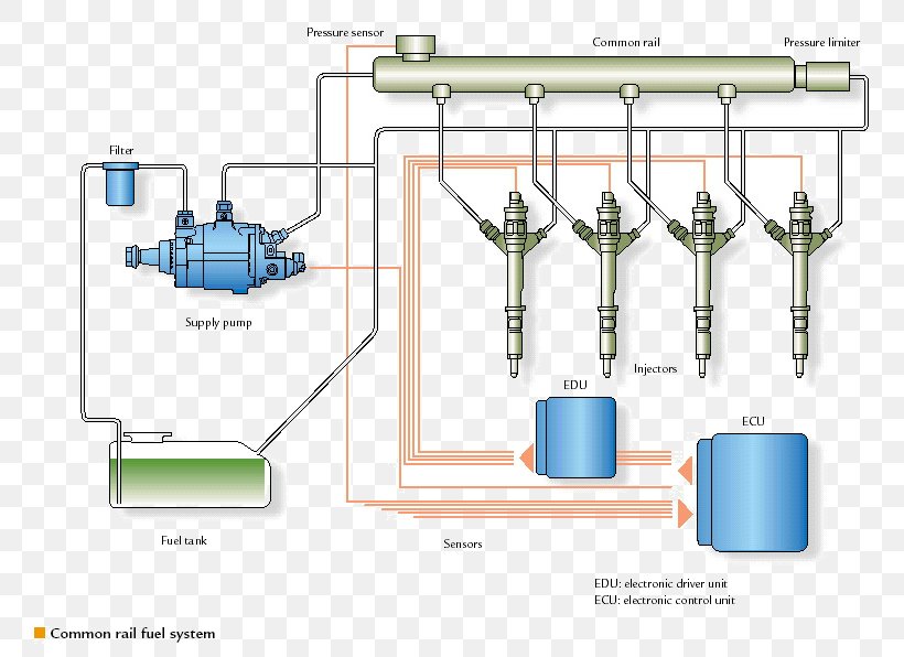
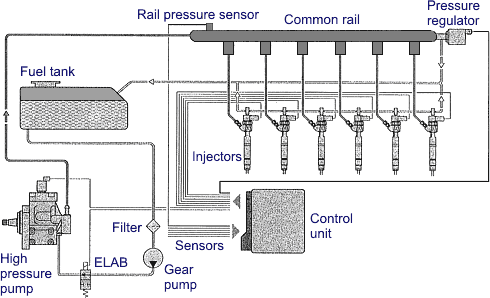
Needle Return Line 13. For the engine to run smoothly and efficiently it needs to be provided with the right quantity of fuelair mixture according to its demands. The Fuel System inside Diesel Engine Fuel System Diagram image size 594 X 438 px and to view image details please click the image.
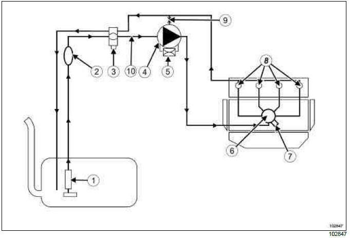
Note ing on pictures will open the diagram page with the big picture on the page that will open again to enlarge the picture. Fuel supply deals with the provision of fuel oil suitable for use by the injection system. Flow diagram of fuel in diesel tractor Cylinder Injector Fuel Diesel Tank Fuel Filter lift pump Filter Fuel injection pump.
Air in fuel system to injection pump. Feb 03 Heres a redneck diagram of the fuel system on a CUmmins ISLISC engine.
A fuel injection system consists of.
In a liquid-cooled diesel the block also provides the structure and rigid frame for the engines cylinders water coolant and oil passages and support for the crankshaft and camshaft bearings. Figure 4 The Cylinder Block. For the engine to run smoothly and efficiently it needs to be provided with the right quantity of fuelair mixture according to its demands. Fuel injection system construction. 1556C 60F for the minimum API gravity of 30 is 08762 and for the maximum API gravity of 45 is. Here is a picture gallery about diesel engine fuel system diagram complete with the description of the image please find the image you need. I observe the lift pump happily pumping fuel through a clear hose into another bucket. Paraffin or wax is a component of diesel fuel. Needle Return Pressure Control Valve 14.
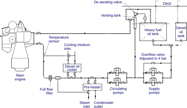
184-405 kW 247-542 hp. 1556C 60F for the minimum API gravity of 30 is 08762 and for the maximum API gravity of 45 is. Air in fuel system to injection pump. A Guide to Properly Diagnose Contamination and Repair Diesel Fuel Systems. The diagram below shows a Fuel oil supply system for a large 2 stroke crosshead engine In the system shown in Figure the oil from the service tank flows through a three-way valve to the supply pump. The Cloud Point represents the temperature when the wax in diesel fuel begins to crystalize and separate from the fuel. Fuel injection system construction.





















Post a Comment for "Diesel Fuel System Diagram"